Adtran
Frads- Adtran Frame Relay Switch-Adtran Frame Relay Switches- Frame Relay Switches-
Telco Frame Relay Switches- Edge Switch-Data Center Switches
For
Information On How Frame Relay Switches Work See Below or Click
Here- For Immediate Information-Call Us At (866) 342-3721
Frame Relay Access Devices (FRADs)
Frame Relay Access Platforms
Frame
Relay DSU/CSUs
Frame Relay Routers
Frame Relay Switch
Integrated
Access Devices
Performance Monitoring
Traffic Shaping
Voice over
Frame Relay
 ACT
2300/1900 for Frame Access
ACT
2300/1900 for Frame Access
- 19" with Single P/S
* D4 channel bank equivalent for FramePort line cards
* Management capabilities
* Useful for customer premises or office co-location
* Redundant power supply
ADTRAN
Frame Relay Switches
Frame
Relay Disaster Recovery
High-Density POTS
High-Speed Serial
Data Transfer
Legacy Data and Voice over Frame Relay
MCK EXTender
7000 and ATLAS 550
Packet Network Emulation
PRI Channel Bankand
Oversubscription
PRI-to-T1 Conversion
Switched Network Emulation
T1 / T3 Voice and Data DACS
Traffic Consolidation

* NEBS compliant
Total
Access 1500 23-Inch Chassis
* Multi-T1 voice and data access platform
* Compact, modular 23" 2U rackmount
chassis with five common and 24 user access slots
* Ideal for high density
POTS deployment
* Supports up to 96 2-wire interfaces
* 67 percent more
dense than a D4 channel back for special services (DDS, ISDN) deployment
*
Terminates up to four T1s, optional protect T1 for TR-08/SLC-96 mode
* Supports
POTS, specials and data
* NEBS Level 3 and UL 1950 compliant
* -40 VDC
to -56 VDC power input
* Optional AC or DC power converter, optional battery
backup available
* Supports fully redundant commons and redundant power feeds
 Total
Frame Relay Access 3000 23" Platform
Total
Frame Relay Access 3000 23" Platform
* 23-inch rackmount available
* 64-pin AMP Champ connectors
minimize wire
wrapping
* Flush or mid-mount
* Dual -48 VDC power feeds
* NEBS Level
3 and UL 1950 compliant

ATLAS
550 Adtran Frads
* Functions as a multi-T1 IAD, 1/0 DACS, NxT1 Inverse Multiplexer, ISDN switch,
IP router, and Frame Relay concentrator/switch
* Switchboard supports circuit
switching applications such as intelligent call routing, overbooking and least-cost
routing based on phone numbers in the dial plan
* Includes IP routing software
with support for PPP and Frame Relay Layer 2 protocols
* DHCP client/ server
* Six-slot modular platform
* Two network interface slots (one T1/PRI module
included with base unit) and four user slots
* Supports up to 18 T1/PRI ports
* Supports E1, PRA, and BRI S/T interfaces for global applications
* Net-3
and Net-5 Euro-ISDN protocols supported
* Maximum backplane bandwidth for
TDM applications is nine T1s through the chassis
* Hot swappable modules
* 10/100BaseT Ethernet LAN interface for SNMP/Telnet management and routing
* AC or DC power
* DC version accepts +24 VDC and -48 VDC input
.
Call
Today (866) Fiber-21 or (866) 650-DATA

Multi
Service Access
VoIP
Channel
Banks
T1/E1 Electrical-to-Optical Converters
Frame Relay
Integrated
Access
Mini DCS
Multiplexers
FTTH
Battery
Backup
Layer
2 Switches ------Multi-
Layer Switches
Stacking
The
TE24 supports stacking features that allow managing up to 8 switches as one unit,
with
a single IP address. The stacking provides the operator with scalability option,
for adding switches into the stack when the ports requirements arise. The stacking
features helps
dramatically in the maintenance and control procedure as the
complete stack, regardless
for the switches number, is treated as a single
entity.
Flexibility
When
more ports are needed, just add another TE24 to the stack and the switches-group
will
look and feel like they are one. Furthermore, plug-in optical transceivers grant
any-optics-type flexibility with any standard SFP in the market use. Telco Systems
optical transceivers variety includes SX, LX, ZX, TX, CWDM and Bi-Directional
miniGBIC types.
Manageability
The
bountiful access avenues, via Web or CLI Tel net, afford network managers simple
and
adequate means to implement network policy. T-Enterprise switches provide
a console port
for the administrators to configure, monitor or manage the network
easily and efficiently.
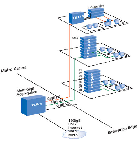
Applications
The
T-Enterprise series is targeted at the Edge arena, providing aggregation services
over
Gigabit Ethernet uplinks for SME (small-to-medium enterprise) operations.
The Edge arena,
also called wiring-closet (when connected in groups), is the
end-customer closest networking
layer, the Metro Access layer. The T-Enterprise
switches helps to connect the access
layer directly to CPE (customer premises
equipment) devices such as PCs, WLAN devices,
IP Telephony devices or other
CPE types, and to provide an intelligence Layer 2 switching
capability for
the services carried out by the CPE devices. The T-Enterprise functionality is
crucial
to reduce the burden form the backbone layer as T-Enterprise family performs even
the
most complicated tasks of the service provider.
Benefits
& Features
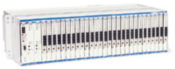
24
10/100BaseTX plus 4 Gigabit Ethernet Enterprise Managed Switch
Targeted at
Edge applications for SMEs
Stacking support (Single-IP management) for up
to 8 units
4 Gigabit Ethernet uplink ports (shared) with maximal flexibility
in choosing between:
• 2 ports 10/100/1000BaseT
• 2 ports unpopulated
miniGBICs (SFP)
Maximal flexibility with plug-in, hot-swap optical transceivers
for SX, LX, ZX, CWDM and Bi-
Directional miniGBIC types
Advanced QoS and
Rate Limiting capabilities
Wire-speed performance with 8.8Gbps non-blocking
switch fabric
Forwarding rate of 6.6MPPS
Multicast support with IGMP Snooping
10K MAC addresses entries
Complete Management options with:
•
SNMPv1/v2C/v3*
• Telnet CLI
• Web-based management
• On-board
console port
Advanced features list including
• 802.1w RSTP on each
port
• 802.1x port authentication
• 802.3ad and LACP support
•
per-port port mirroring
• 64 static VLANs
• Broadcast Storm Control
Extremely low power consumption with only 21W!
FCC and CE certified
Frame
Relay
Introduction
Frame
Relay is a high-performance WAN protocol that operates at the physical and data
link layers of the OSI reference model. Frame Relay originally was designed for
use across Integrated Services Digital Network (ISDN) interfaces. Today, it is
used over a variety of other network interfaces as well. This chapter focuses
on Frame Relay's specifications and applications in the context of WAN services.
Frame
Relay is an example of a packet-switched technology. Packet-switched networks
enable end stations to dynamically share the network medium and the available
bandwidth. The following two techniques are used in packet-switching technology:
•Variable-length
packets
•Statistical
multiplexing
Variable-length
packets are used for more efficient and flexible data transfers. These packets
are switched between the various segments in the network until the destination
is reached.
Statistical
multiplexing techniques control network access in a packet-switched network. The
advantage of this technique is that it accommodates more flexibility and more
efficient use of bandwidth. Most of today's popular LANs, such as Ethernet and
Token Ring, are packet-switched networks.
Frame
Relay often is described as a streamlined version of X.25, offering fewer of the
robust capabilities, such as windowing and retransmission of last data that are
offered in X.25. This is because Frame Relay typically operates over WAN facilities
that offer more reliable connection services and a higher degree of reliability
than the facilities available during the late 1970s and early 1980s that served
as the common platforms for X.25 WANs. As mentioned earlier, Frame Relay is strictly
a Layer 2 protocol suite, whereas X.25 provides services at Layer 3 (the network
layer) as well. This enables Frame Relay to offer higher performance and greater
transmission efficiency than X.25, and makes Frame Relay suitable for current
WAN applications, such as LAN interconnection.
Frame Relay Standardization
Initial
proposals for the standardization of Frame Relay were presented to the Consultative
Committee on International Telephone and Telegraph (CCITT) in 1984. Because of
lack of interoperability and lack of complete standardization, however, Frame
Relay did not experience significant deployment during the late 1980s.
A
major development in Frame Relay's history occurred in 1990 when Cisco, Digital
Equipment Corporation (DEC), Northern Telecom, and StrataCom formed a consortium
to focus on Frame Relay technology development. This consortium developed a specification
that conformed to the basic Frame Relay protocol that was being discussed in CCITT,
but it extended the protocol with features that provide additional capabilities
for complex internetworking environments. These Frame Relay extensions are referred
to collectively as the Local Management Interface (LMI).
Since
the consortium's specification was developed and published, many vendors have
announced their support of this extended Frame Relay definition. ANSI and CCITT
have subsequently standardized their own variations of the original LMI specification,
and these standardized specifications now are more commonly used than the original
version.
Internationally,
Frame Relay was standardized by the International Telecommunication Union—Telecommunications
Standards Section (ITU-T). In the United States, Frame Relay is an ATEK Communications National
Standards Institute (ANSI) standard.
Frame Relay Devices
Devices
attached to a Frame Relay WAN fall into the following two general categories:
•Data
terminal equipment (DTE)
•Data
circuit-terminating equipment (DCE)
DTEs
generally are considered to be terminating equipment for a specific network and
typically are located on the premises of a customer. In fact, they may be owned
by the customer. Examples of DTE devices are terminals, personal computers, routers,
and bridges.
DCEs
are carrier-owned internetworking devices. The purpose of DCE equipment is to
provide clocking and switching services in a network, which are the devices that
actually transmit data through the WAN. In most cases, these are packet switches.
Figure 10-1 shows the relationship between the two categories of devices.
Figure
10-1 DCEs Generally Reside Within Carrier-Operated WANs
The
connection between a DTE device and a DCE device consists of both a physical layer
component and a link layer component. The physical component defines the mechanical,
electrical, functional, and procedural specifications for the connection between
the devices. One of the most commonly used physical layer interface specifications
is the recommended standard (RS)-232 specification. The link layer component defines
the protocol that establishes the connection between the DTE device, such as a
router, and the DCE device, such as a switch. This chapter examines a commonly
utilized protocol specification used in WAN networking: the Frame Relay protocol.
Frame
Relay Virtual Circuits
Frame
Relay provides connection-oriented data link layer communication. This means that
a defined communication exists between each pair of devices and that these connections
are associated with a connection identifier. This service is implemented by using
a Frame Relay virtual circuit, which is a logical connection created between two
data terminal equipment (DTE) devices across a Frame Relay packet-switched network
(PSN).
Virtual
circuits provide a bidirectional communication path from one DTE device to another
and are uniquely identified by a data-link connection identifier (DLCI). A number
of virtual circuits can be multiplexed into a single physical circuit for transmission
across the network. This capability often can reduce the equipment and network
complexity required to connect multiple DTE devices.
A
virtual circuit can pass through any number of intermediate DCE devices (switches)
located within the Frame Relay PSN.
Frame
Relay virtual circuits fall into two categories: switched virtual circuits (SVCs)
and permanent virtual circuits (PVCs).
Switched Virtual Circuits
Switched
virtual circuits (SVCs) are temporary connections used in situations requiring
only sporadic data transfer between DTE devices across the Frame Relay network.
A communication session across an SVC consists of the following four operational
states:
•Call
setup—The virtual circuit between two Frame Relay DTE devices is established.
•Data
transfer—Data is transmitted between the DTE devices over the virtual circuit.
•Idle—The
connection between DTE devices is still active, but no data is transferred. If
an SVC remains in an idle state for a defined period of time, the call can be
terminated.
•Call
termination—The virtual circuit between DTE devices is terminated.
After
the virtual circuit is terminated, the DTE devices must establish a new SVC if
there is additional data to be exchanged. It is expected that SVCs will be established,
maintained, and terminated using the same signaling protocols used in ISDN.
Few
manufacturers of Frame Relay DCE equipment support switched virtual circuit connections.
Therefore, their actual deployment is minimal in today's Frame Relay networks.
Previously
not widely supported by Frame Relay equipment, SVCs are now the norm. Companies
have found that SVCs save money in the end because the circuit is not open all
the time.
Permanent Virtual Circuits
Permanent
virtual circuits (PVCs) are permanently established connections that are used
for frequent and consistent data transfers between DTE devices across the Frame
Relay network. Communication across a PVC does not require the call setup and
termination states that are used with SVCs. PVCs always operate in one of the
following two operational states:
•Data
transfer—Data is transmitted between the DTE devices over the virtual circuit.
•Idle—The
connection between DTE devices is active, but no data is transferred. Unlike SVCs,
PVCs will not be terminated under any circumstances when in an idle state.
DTE
devices can begin transferring data whenever they are ready because the circuit
is permanently established.
Data-Link Connection Identifier
Frame
Relay virtual circuits are identified by data-link connection identifiers (DLCIs).
DLCI values typically are assigned by the Frame Relay service provider (for example,
the telephone company).
Frame
Relay DLCIs have local significance, which means that their values are unique
in the LAN, but not necessarily in the Frame Relay WAN.
Figure
10-2 illustrates how two different DTE devices can be assigned the same DLCI value
within one Frame Relay WAN.
Figure
10-2 A Single Frame Relay Virtual Circuit Can Be Assigned Different DLCIs on Each
End of a VC
Congestion-Control
Mechanisms
Frame
Relay reduces network overhead by implementing simple congestion-notification
mechanisms rather than explicit, per-virtual-circuit flow control. Frame Relay
typically is implemented on reliable network media, so data integrity is not sacrificed
because flow control can be left to higher-layer protocols. Frame Relay implements
two congestion-notification mechanisms:
•Forward-explicit
congestion notification (FECN)
•Backward-explicit
congestion notification (BECN)
FECN
and BECN each is controlled by a single bit contained in the Frame Relay frame
header. The Frame Relay frame header also contains a Discard Eligibility (DE)
bit, which is used to identify less important traffic that can be dropped during
periods of congestion.
The
FECN bit is part of the Address field in the Frame Relay frame header. The FECN
mechanism is initiated when a DTE device sends Frame Relay frames into the network.
If the network is congested, DCE devices (switches) set the value of the frames'
FECN bit to 1. When the frames reach the destination DTE device, the Address field
(with the FECN bit set) indicates that the frame experienced congestion in the
path from source to destination. The DTE device can relay this information to
a higher-layer protocol for processing. Depending on the implementation, flow
control may be initiated, or the indication may be ignored.
The
BECN bit is part of the Address field in the Frame Relay frame header. DCE devices
set the value of the BECN bit to 1 in frames traveling in the opposite direction
of frames with their FECN bit set. This informs the receiving DTE device that
a particular path through the network is congested. The DTE device then can relay
this information to a higher-layer protocol for processing. Depending on the implementation,
flow-control may be initiated, or the indication may be ignored.
Frame Relay
Discard Eligibility
The
Discard Eligibility (DE) bit is used to indicate that a frame has lower importance
than other frames. The DE bit is part of the Address field in the Frame Relay
frame header.
DTE
devices can set the value of the DE bit of a frame to 1 to indicate that the frame
has lower importance than other frames. When the network becomes congested, DCE
devices will discard frames with the DE bit set before discarding those that do
not. This reduces the likelihood of critical data being dropped by Frame Relay
DCE devices during periods of congestion.
Frame Relay Error Checking
Frame
Relay uses a common error-checking mechanism known as the cyclic redundancy check
(CRC). The CRC compares two calculated values to determine whether errors occurred
during the transmission from source to destination. Frame Relay reduces network
overhead by implementing error checking rather than error correction. Frame Relay
typically is implemented on reliable network media, so data integrity is not sacrificed
because error correction can be left to higher-layer protocols running on top
of Frame Relay.
Frame Relay Local Management Interface
The
Local Management Interface (LMI) is a set of enhancements to the basic Frame Relay
specification. The LMI was developed in 1990 by Cisco Systems, StrataCom, Northern
Telecom, and Digital Equipment Corporation. It offers a number of features (called
extensions) for managing complex internetworks. Key Frame Relay LMI extensions
include global addressing, virtual circuit status messages, and multicasting.
The
LMI global addressing extension gives Frame Relay data-link connection identifier
(DLCI) values global rather than local significance. DLCI values become DTE addresses
that are unique in the Frame Relay WAN. The global addressing extension adds functionality
and manageability to Frame Relay internetworks. Individual network interfaces
and the end nodes attached to them, for example, can be identified by using standard
address-resolution and discovery techniques. In addition, the entire Frame Relay
network appears to be a typical LAN to routers on its periphery.
LMI
virtual circuit status messages provide communication and synchronization between
Frame Relay DTE and DCE devices. These messages are used to periodically report
on the status of PVCs, which prevents data from being sent into black holes (that
is, over PVCs that no longer exist).
The
LMI multicasting extension allows multicast groups to be assigned. Multicasting
saves bandwidth by allowing routing updates and address-resolution messages to
be sent only to specific groups of routers. The extension also transmits reports
on the status of multicast groups in update messages.
Frame Relay Network Implementation
A
common private Frame Relay network implementation is to equip a T1 multiplexer
with both Frame Relay and non-Frame Relay interfaces. Frame Relay traffic is forwarded
out the Frame Relay interface and onto the data network. Non-Frame Relay traffic
is forwarded to the appropriate application or service, such as a private branch
exchange (PBX) for telephone service or to a video-teleconferencing application.
A
typical Frame Relay network consists of a number of DTE devices, such as routers,
connected to remote ports on multiplexer equipment via traditional point-to-point
services such as T1, fractional T1, or 56-Kb circuits. An example of a simple
Frame Relay network is shown in Figure 10-3.
Figure
10-3 A Simple Frame Relay Network Connects Various Devices to Different Services
over a WAN
The
majority of Frame Relay networks deployed today are provisioned by service providers
that intend to offer transmission services to customers. This is often referred
to as a public Frame Relay service. Frame Relay is implemented in both public
carrier-provided networks and in private enterprise networks. The following section
examines the two methodologies for deploying Frame Relay.
Public Carrier-Provided
Networks
In
public carrier-provided Frame Relay networks, the Frame Relay switching equipment
is located in the central offices of a telecommunications carrier. Subscribers
are charged based on their network use but are relieved from administering and
maintaining the Frame Relay network equipment and service.
Generally,
the DCE equipment also is owned by the telecommunications provider.
DTE equipment
either will be customer-owned or perhaps will be owned by the telecommunications
provider as a service to the customer.
The
majority of today's Frame Relay networks are public carrier-provided networks.
Private
Enterprise Networks
More
frequently, organizations worldwide are deploying private Frame Relay networks.
In private Frame Relay networks, the administration and maintenance of the network
are the responsibilities of the enterprise (a private company). All the equipment,
including the switching equipment, is owned by the customer.
Frame Relay Frame
Formats
To
understand much of the functionality of Frame Relay, it is helpful to understand
the structure of the Frame Relay frame. Figure 10-4 depicts the basic format of
the Frame Relay frame, and Figure 10-5 illustrates the LMI version of the Frame
Relay frame.
Flags
indicate the beginning and end of the frame. Three primary components make up
the
Frame Relay frame: the header and address area, the user-data portion, and the
frame check sequence (FCS). The address area, which is 2 bytes in length, is comprised
of 10
bits representing the actual circuit identifier and 6 bits of fields
related to congestion management. This identifier commonly is referred to as the
data-link connection identifier (DLCI). Each of these is discussed in the descriptions
that follow.
Standard Frame Relay Frame
Standard
Frame Relay frames consist of the fields illustrated in Figure 10-4.
Figure
10-4 Five Fields Comprise the Frame Relay Frame
The
following descriptions summarize the basic Frame Relay frame fields illustrated
in Figure 10-4.
•Flags—Delimits
the beginning and end of the frame. The value of this field is always the same
and is represented either as the hexadecimal number 7E or as the binary number
01111110.
•Address—Contains
the following information:
–DLCI—The
10-bit DLCI is the essence of the Frame Relay header. This value represents the
virtual connection between the DTE device and the switch. Each virtual connection
that is multiplexed onto the physical channel will be represented by a unique
DLCI. The DLCI values have local significance only, which means that they are
unique only to the physical channel on which they reside. Therefore, devices at
opposite ends of a connection can use different DLCI values to refer to the same
virtual connection.
–Extended
Address (EA)—The EA is used to indicate whether the byte in which the EA
value is 1 is the last addressing field. If the value is 1, then the current byte
is determined to be the last DLCI octet. Although current Frame Relay implementations
all use a two-octet DLCI, this capability does allow longer DLCIs to be used in
the future. The eighth bit of each byte of the Address field is used to indicate
the EA.
–C/R—The
C/R is the bit that follows the most significant DLCI byte in the Address field.
The C/R bit is not currently defined.
–Congestion
Control—This consists of the 3 bits that control the Frame Relay congestion-notification
mechanisms. These are the FECN, BECN, and DE bits, which are the last 3 bits in
the Address field.
Forward-explicit
congestion notification (FECN) is a single-bit field that can be set to a value
of 1 by a switch to indicate to an end DTE device, such as a router, that congestion
was experienced in the direction of the frame transmission from source to destination.
The primary benefit of the use of the FECN and BECN fields is the capability of
higher-layer protocols to react intelligently to these congestion indicators.
Today, DECnet and OSI are the only higher-layer protocols that implement these
capabilities.
Backward-explicit
congestion notification (BECN) is a single-bit field that, when set to a value
of 1 by a switch, indicates that congestion was experienced in the network in
the direction opposite of the frame transmission from source to destination.
Discard
eligibility (DE) is set by the DTE device, such as a router, to indicate that
the marked frame is of lesser importance relative to other frames being transmitted.
Frames that are marked as "discard eligible" should be discarded before
other frames in a congested network. This allows for a basic prioritization mechanism
in Frame Relay networks.
•Data—Contains
encapsulated upper-layer data. Each frame in this variable-length field includes
a user data or payload field that will vary in length up to 16,000 octets. This
field serves to transport the higher-layer protocol packet (PDU) through a Frame
Relay network.
•Frame
Check Sequence—Ensures the integrity of transmitted data. This value is computed
by the source device and verified by the receiver to ensure integrity of transmission.
LMI
Frame Format
Frame
Relay frames that conform to the LMI specifications consist of the fields illustrated
in Figure 10-5.
Figure
10-5 Nine Fields Comprise the Frame Relay That Conforms to the LMI Format
The
following descriptions summarize the fields illustrated in Figure 10-5.
•Flag—Delimits
the beginning and end of the frame.
•LMI
DLCI—Identifies the frame as an LMI frame instead of a basic Frame Relay
frame. The LMI-specific DLCI value defined in the LMI consortium specification
is DLCI = 1023.
•Unnumbered
Information Indicator—Sets the poll/final bit to zero.
•Protocol
Discriminator—Always contains a value indicating that the frame is an LMI
frame.
•Call
Reference—Always contains zeros. This field currently is not used for any
purpose.
•Message
Type—Labels the frame as one of the following message types:
–Status-inquiry
message—Allows a user device to inquire about the status of the network.
–Status
message—Responds to status-inquiry messages. Status messages include keepalives
and PVC status messages.
•Information
Elements—Contains a variable number of individual information elements (IEs).
IEs consist of the following fields:
–IE
Identifier—Uniquely identifies the IE.
–IE
Length—Indicates the length of the IE.
–Data—Consists
of 1 or more bytes containing encapsulated upper-layer data.
•Frame
Check Sequence (FCS)—Ensures the integrity of transmitted data.
Summary
Frame
Relay is a networking protocol that works at the bottom two levels of the OSI
reference model: the physical and data link layers. It is an example of packet-switching
technology, which enables end stations to dynamically share network resources.
Frame
Relay devices fall into the following two general categories:
•Data
terminal equipment (DTEs), which include terminals, personal computers, routers,
and bridges
•Data
circuit-terminating equipment (DCEs), which transmit the data through the network
and are often carrier-owned devices (although, increasingly, enterprises are buying
their own DCEs and implementing them in their networks)
Frame
Relay networks transfer data using one of the following two connection types:
•Switched
virtual circuits (SVCs), which are temporary connections that are created for
each data transfer and then are terminated when the data transfer is complete
(not a widely used connection)
•Permanent
virtual circuits (PVCs), which are permanent connections
The
DLCI is a value assigned to each virtual circuit and DTE device connection point
in the Frame Relay WAN. Two different connections can be assigned the same value
within the same Frame Relay WAN—one on each side of the virtual connection.
In
1990, Cisco Systems, StrataCom, Northern Telecom, and Digital Equipment Corporation
developed a set of Frame Relay enhancements called the Local Management Interface
(LMI). The LMI enhancements offer a number of features (referred to as extensions)
for managing complex internetworks, including the following:
•Global
addressing
•Virtual
circuit status messages
•Multicasting
West
Coast (866) 342-3721 ------East
Coast (866) 650-DATA


